Stable Т-tripod for solar eclipse photography
July 28, 2023
Introduction
During the lockdown of 2020, I designed a stable and compact tripod, which allows for precise polar alignment. The tripod consists of readily available components (except one). The tripod is very convenient for transportation. Its weight is only 4 kg. Being disassembled, it occupies a volume of only approximately 60x10x5 cm. Thus, it is well-suited for expeditions to remote regions of the Earth, such as observing solar eclipses. The first version I created for photographing the solar eclipse on December 14, 2020.
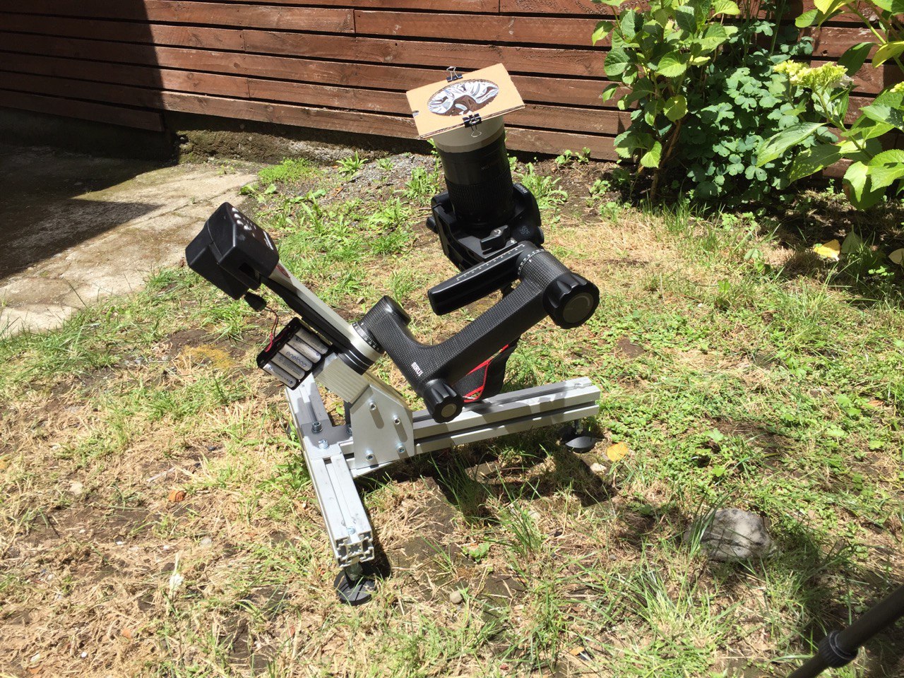 The first version of the tripod with tracker, gimbal head, and camera attached
A common problem when photographing the full phase of a solar eclipse is the instability of the camera tripod or telescope mount. The cost of choosing the wrong tripod for photographing a total solar eclipse is significant, as it may ruin the capture of such a rare event, and there is no second attempt.
Here, I will provide a detailed description of my exceptionally stable tripod so that anyone interested can replicate and use it. Of course, the use of this tripod is not limited to capturing solar eclipses; it can be utilized for more standard night astrophotography.
Tripod Overview
The tripod consists of a T-shaped frame, three screw supports, and an equatorial wedge. The 3D model in OpenSCAD format can be found in the GitHub repository. A list of all the necessary components, except for the equatorial wedge, is available in the Google Spreadsheet. The equatorial wedge is the only component that needs to be manufactured by the reader.
Frame
The frame consists of two segments of industrial aluminum profile with a cross-section of 45x45 mm. This type of profile has standard mounting slots along its length. T-nuts are inserted into these slots, and the necessary components are fastened with screws. This kind of profile is widely used for constructing various structures, and it can be easily ordered with delivery. There, you can also purchase other components, such as connecting plates, fasteners, and supporting screws. When ordering, you need to specify the required length for the cut. Also, three holes are necessary in the profile for mounting supports on the frame. One hole should be drilled in the short profile, and two holes in the long one. The holes should have a diameter of 17 mm, and their center should be 45 mm from the edge. Threaded bushings for the supporting screws are pressed into these holes from the bottom.
The dimensions of the frame sides are 400 mm and 552 mm. The short side is oriented in the north-south direction, while the long side faces west-east. The side lengths are chosen so that the supporting screws are located at the corners of an equilateral triangle. The reader can proportionally adjust the side dimensions at their discretion, although the current values are close to optimal.
The profiles are connected with an A-shaped plate at the bottom and a T-shaped plate at the top. The A-shaped plate serves as a strengthening rib. The top plate must be T-shaped to allow for longitudinal movement of the equatorial wedge. It is advisable to position the wedge so that the center of mass of the entire system (including the tracker, camera, and lens) is projected as close to the center of the triangle as possible.
Screw Supports
The support is provided by an M12 screw with a ball head and nut. The head fits into a metal pad with the appropriate recess. The screw thread is located in two places: in the threaded bushing (at the bottom) and in the adapter (at the top). This allows adjusting the thread gap and eliminating backlash. The procedure for eliminating backlash is described below. The adapter is attached to the frame using T-nuts and screws, while the bushing is pressed into the hole or carefully hammered in.

The polar axis of the tracker is aligned using these screws. By rotating the front screw, the height of the polar axis is adjusted.
By rotating the right and left screws, the azimuth of the polar axis of the tracker is adjusted.
Equatorial Wedge
The equatorial wedge is used to attach the star tracker to the tripod and roughly set the height of the polar axis of the tracker. The wedge is secured to the frame with angular connecting plates. These plates are available for sale with angles of 0, 15, 30, 45, 60, and 90 degrees.
The wedge has three pairs of holes, allowing it to be shifted to five different positions relative to the plate’s angle: -10, -5, 0, +5, +10 degrees. In combination with various angular connecting plates, the entire range from 0 to 90 degrees can be covered in 5-degree increments. The final alignment of the polar axis is done with the support screws.
The equatorial wedge shown in the animations is designed for mounting the Fornax LightTrack II tracker. It is attached directly to the wedge with two M6 screws. Many other tracker models are mounted using a “dovetail” clamp, for which different mounting holes in the wedge need to be provided. As mentioned earlier, this is the only component of the tripod that the reader needs to manufacture.
Tall Version of the Tripod with a Vertical Column
If the mounting height of the tracker is insufficient, you can install an additional vertical column made of 45x90 mm profile. The column is attached to the tripod with two L-shaped connecting plates and one A-shaped plate.
Polar Alignment
Polar alignment can be done manually, but it can be quite inconvenient. Therefore, I developed a program called Tune → GitHub, which significantly simplifies this process. The program works using the blind astrometry algorithm astrometry.net and allows you to calculate the deviation from the polar axis using either two images of the area near the pole or three arbitrary images. After determining the deviation, the magnitude and direction of adjustments for the support screws are calculated. The same lens and camera used for subsequent sky photography are used for polar axis alignment. No additional equipment is required (except for a computer). The program is operated and controlled from the terminal command line.
Detailed documentation for this program will be provided later.
Feedback
I hope that this design can be helpful to the community. I will be glad to answer questions, read comments, and consider suggestions. Do not hesitate to write me k@homb.it.
Appendix: Eliminating Backlash of Support Screw
To eliminate backlash in the support screw, you need to unscrew the adapter screws, rotate it 180 degrees, and screw the adapter screws back in and tighten them. When rotating the adapter, a small gap is formed between it and the frame, and when tightening the screws, this gap disappears due to the shift of the threaded bushing downwards. This securely presses the support screw against the adapter and bushing threads, eliminating backlash. If the bushing comes out too far after several attempts to eliminate backlash, it can be hammered back in, first unscrewing the support screw.